Connecting a table football table to the Internet of Things
This is my first Arduino project. The idea is to make possibly the first tweeting table football table to join the Internet of Things. You see the table at my company is in the kitchen that is in an annex of the office. The goal (pun intended) was to publish the availability of the table to potentially interested players.
The design is simple: I used a piezoelectric knock sensor strapped under the table to detect shocks. That’s very easy with an Arduino board. Actually it’s one of the first examples on the Arduino web site so I won’t get in the details of the electronics. The important thing is that it works perfectly. The shallow wooden table acts as a sound box so the sensor is able to pick up the slightest nudge. And the legs of the table are stiff and heavy enough to avoid that the sensor picks up vibrations from people walking by.
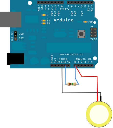
(c) Arduino
So the only matters remaining are power and connectivity. There is no wired network near the table and I didn’t want to have power or ethernet cables running from the table anyway. So I needed a battery and a wireless communication system. I bought the biggest LiPo battery I could find (6Ah) and a WiFly shield. First let me say that the WiFly shield is seriously awesome. In a day or so I was able to make the WiFly connect to my secured wireless network, acquire an IP address via DHCP and serve a webpage indicating the last reading of the knock sensor. That looked promising but after some testing I started to realise that connections to the HTTP server were often failing. I knew that the Wi-Fi signal was weak but that was not all. The Wi-Fly also had trouble handling concurrent client connections. You see there is no multi-threading with Arduinos. The Wi-Fly is buffering some of the network traffic so if you respond to requests fast enough, you can get to the next request in time before it times out. But that’s not reliable. And that was not even the biggest problem. The battery lasted only a few hours. To make this project viable, I needed at least a few days of battery life.
So I was back to the drawing board. If I am not using Wi-Fi, maybe I could use another kind of radio-communication. I know nothing about radios so I was worried that I would not be able to figure it out. But after some research, I discovered XBees. XBees are very versatile radio modules that can work in all sorts of situations. For this project I had only needed a point-to-point connection from the Arduino board under the table to a receiver somewhere close by. But XBees can do much more than that. You can create a whole mesh network of them sharing and passing packets all over the place. One XBee can send data to all the XBees around or target a specific XBee ID (kind of like an IP address). It’s really cool stuff.
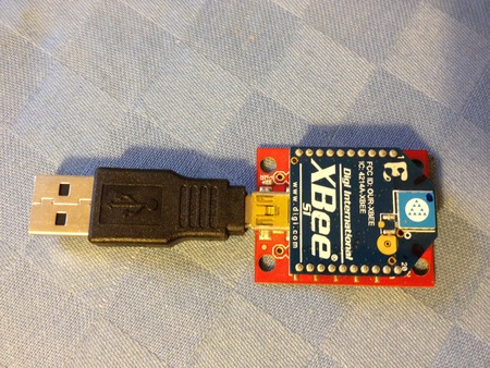
The XBees can be configured easily using the XBee Explorer USB board (or the USB dongle version) and the X-CTU software (Windows only) as explained in this tutorial. You can download the XBee configuration file for the the sender XBee here.
To plug an XBee on a standard Arduino board, you can use an XBee shield. But an even simpler solution is to use an Arduino Fio board. That little board has an XBee socket directly on it. It also has a socket for the LiPo battery and a USB plug to recharge the battery. It makes the all thing very compact and convenient. You just have to remember to remove the XBee every time you want to upload a new sketch to the board. You can also upload sketches wirelessly but many people on the Net seemed to have trouble doing this so I went with the easier solution: USB. The USB plug on the Fio board is for power only so you need an FTDI Serial to USB adapter. It’s all explained here and here.
I started to code my Arduino sketch based on the knock example on the Arduino site. To reduce the quantity of packets sent by the XBee, I decided to sum the sensor readings together and send the total amount about once a second (only if it’s above a certain threshold). Because the board is not transmitting when there is no shock, I couldn't tell when I was not receiving any data if it was because nothing was happening or if the battery was dead. Luckily I found a nice trick to read the power level of the battery so I decided to send that too, once every ten minutes. If I don’t receive at least one packet every ten minutes, I know that something is wrong. You can download my Arduino sketch source code GitHub.
Let’s summarise the parts required so far:
- 2 XBee Series 1 modules
- 1 Arduino Fio board
- 1 piezoelectric knock sensor
- 1 1 ohm resistor
- 1 XBee Explorer USB or Dongle
- 1 FTDI Break Out board (3.3 V)
- 1 USB to USB mini cable
- 1 5V USB power adapter
- 1 set of stackable headers forthe Fio board
- 1 extra 6-pin header (preferably a right angle one) for the FTDI break Out board
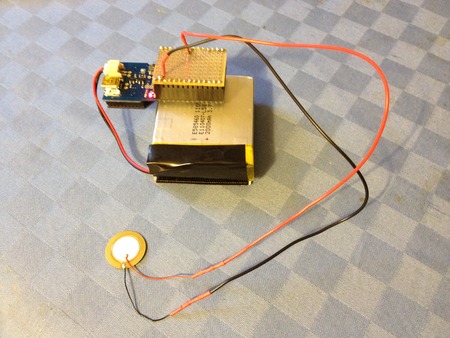
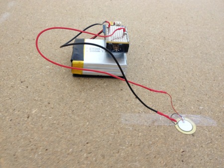
In my case I put the sensor and the resistor on a small perfboard so that I could easily put or remove them all at once when I need to upload a new sketch. It is the only soldering that was required in the whole project! That’s the magic of Arduino.
The Arduino Fio is attached to the battery pack using piece of Velcro and the whole thing is attached upside down to the bottom of the table thanks to an even bigger piece of Velcro. Velcro is awesome.
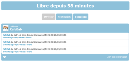
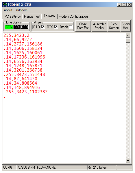
The configuration of the XBee on the receiving end is available here. It is connected to a Linux server and I use the xbee-api Java library to read the incoming data. You can see the status page and also on Twitter. Below you can see the data packets coming in. The first value identifies the packet type (255 is power, 14 is shock), the second value is the actual sensor value and the third is the number of milliseconds since the last reset of the Arduino.
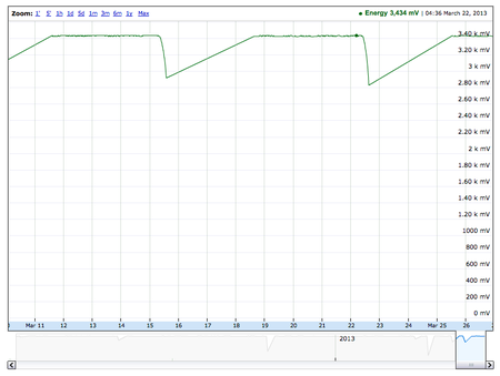
The battery lasts almost 5 days. It means I have to recharge it overnight once or twice a week. That's good enough. Also I noticed that the power is quite stable (near 3.4V) until a about an hour before the battery runs out (around 2.8V). So I added an e-mail alert on the linux server to be notified when the power drops below 3.3V. It's pretty convenient.
The project has been running smoothly for several months now and I didn't have a single glitch. The stability of the Linux system, the Arduino board and the XBees is very impressive. I think the LAXB stack offers tremendous possibilities to the maker community and I hope that this project will inspire others to give it a try.
Short URL for this post: http://lepl.us/1b